Parting line in injection molding are the lines where the mold halves meet, marking the separation between the core and cavity sections, These lines are unavoidable due to the necessity of removing parts from the mold after molding. Keep reading to learn more about parting lines in injection molding. This article will explore parting line basics, locations, types, and design considerations.
What is the Parting Line in Injection Molding?
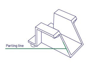
A parting line is a visible line or seam on a custom plastic molded part where the two halves of the injection mold meet. When the mold is closed and the molten plastic is injected into the cavity, the material fills the space created by the mold halves. Once the plastic solidifies and the mold opens, the parting line appears where the two halves are separated. This line can vary in appearance depending on the design of the mold and the molded part’s geometry. The parting line is an inevitable feature of the injection molding process, and its design and placement are critical to the final product’s quality and functionality.
Properly positioned parting lines can minimize visible flaws and ensure accurate part geometry, facilitating easier mold assembly, part removal, and a better final product appearance. Conversely, poorly placed parting lines can lead to defects, leaks, and visual imperfections.
How Parting Lines Are Formed?
The formation of parting lines in injection molding is a result of the molding process itself, rather than an injection molding defect. The injection mold is typically divided into two halves – the fixed half and the moving half. The parting line appears on the molded part where the two mold halves meet, typically running around the entire perimeter of the part. In most cases, the parting line is perpendicular to the opening direction of the mold.
For more complex parts, the mold structure may be parted multiple times from various directions, a process known as multi-step parting. The parting line is an inevitable result of the need to open the mold and remove the finished part. its location and characteristics are determined during the mold design phase.
Types of Parting Line in Injection Molding
There are several types of parting lines in injection molding, each suited to different part geometries and complexities. Here are the main types:
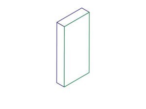
1. Vertical Parting Line
Vertical parting lines are perpendicular to the direction in which the mold opens. It is the most basic and popular type. They are commonly seen along the edges of simple parts like Lego blocks.
2. Beveled Parting Line
A beveled parting line has sloping edges instead of straight ones, which can help reduce flash formation. Features like fibs might trap air if not beveled.
3. Curved Parting Line
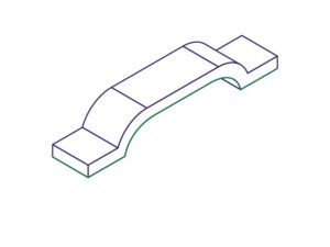
A curved parting line is used for parts with curved surfaces, these parting lines follow the contour of the part. For example, An injection-molded drill housing might require a curved parting line to accommodate areas like the trigger.
4. Stepped Parting Line
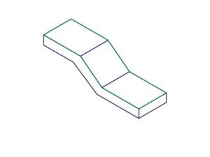
A stepped parting line involves multiple levels or steps in the mold interface. This type is used for parts with varying thicknesses or intricate designs where a single. Stepped parting lines can provide better control over part ejection and reduce the likelihood of defects.
5. Comprehensive Parting Line
A comprehensive parting line incorporates features of vertical, beveled, curved, and stepped parting lines within a single mold. This approach is used for highly complex parts that require different parting line strategies to accommodate various features and geometries. Comprehensive parting lines allow for greater design flexibility and optimization.
Why Does Parting Line in Injection Molding Location Matter?
- The parting line’s location significantly impacts the visual appearance of the final product. Well-placed parting lines can minimize visible flaws and seams on the part’s surface.
- The parting line position influences where other features can be placed on the part. Placing important features on the wrong side of the parting line could lead to serious issues with the injection molding process.
- Properly positioned parting lines help ensure accurate part geometry and structural integrity. Poor placement can lead to defects, leaks, and imperfections in the final product.
- The parting line location affects the ease of mold assembly, part removal, and overall manufacturing efficiency. Strategic placement can simplify production and reduce costs.
- The parting line is crucial in determining the mold design, including factors like the line of draw, draft angles, and placement of components.
- Well-designed parting lines can help minimize common molding defects like flash formation and alignment issues.
Optimize Parting Lines in Injection Molding Practices
Designing molds to optimize parting lines is crucial for ensuring high-quality, functional, and aesthetically pleasing injection-molded parts. Here are some best practices to follow.
- Place parting lines in less visible areas to enhance the final product’s appearance. For example, align parting lines with natural edges or contours of the part. Position parting lines away from intricate details, undercuts, or complex geometric features to reduce the risk of defects and flash formation.
- Align parting lines with the part’s geometry to maintain structural integrity and ease of mold release. Symmetrical parting lines help in achieving balanced mold designs, which facilitate uniform material flow and reduce stress points.
- Incorporate appropriate draft angles to ensure smooth ejection of the part from the mold, preventing damage and maintaining part quality.
- Different materials exhibit varied shrinkage and characteristics. Design the mold to account for plastic shrinkage during cooling ensuring that the part maintains its intended dimensions and features.
- Consider the “line of draw” -the mold opening direction relative to the part. This impacts part design and feature placement.
Different Injection Molding Lines
Except for parting lines, various types of injection molding lines can appear on plastic or rubber or PU molded parts, each resulting from different reasons during the molding process. Here, we compare weld lines, knit lines, and flow lines in terms of their formation, appearance, impact on the final product, and how to solve the defects.
Weld Molding Lines
Weld Lines, also called Meld Lines, occur when two or more flow fronts meet during mold filling, typically around holes or inserts. They are often visible as a line or seam on the part surface.
The weld lines are caused by multiple gates, obstacles in the flow path, or complex part geometry.
They can create weak points in the part, potentially reducing strength by 10-50%.
Optimizing gate locations, increasing melt and mold temperatures, and adjusting injection speed will prevent the weld lines.
Knit Molding Lines
Knit lines injection molding are similar to weld lines, and form when flow fronts meet but under less pressure. They are less visible than weld lines but still detectable.
Similar to weld lines, optimizing gate locations, increasing temperatures, and adjusting injection parameters will eliminate the knit lines.
Flow Molding Lines
Flow lines result from variations in cooling rates or material flow during injection. They appear as wavy or rippled patterns on the part surface, often parallel to the flow direction.
The flow lines are primarily an aesthetic issue and typically don’t affect mechanical properties.
Rapid cooling, variations in wall thickness, or improper gate location will cause the flow lines in plastic parts.
Adjusting mold and melt temperatures, optimizing gate location and size, and modifying wall thickness will avoid the flow lines.
Parting Lines Conclusion
The location of the parting line in injection molding affects aesthetics, functionality, part quality, and manufacturability. Proper placement minimizes visible flaws and ensures accurate part geometry. Optimize parting line placement by considering part geometry, draft angles, and material properties to ensure efficient manufacturing and high-quality parts.


